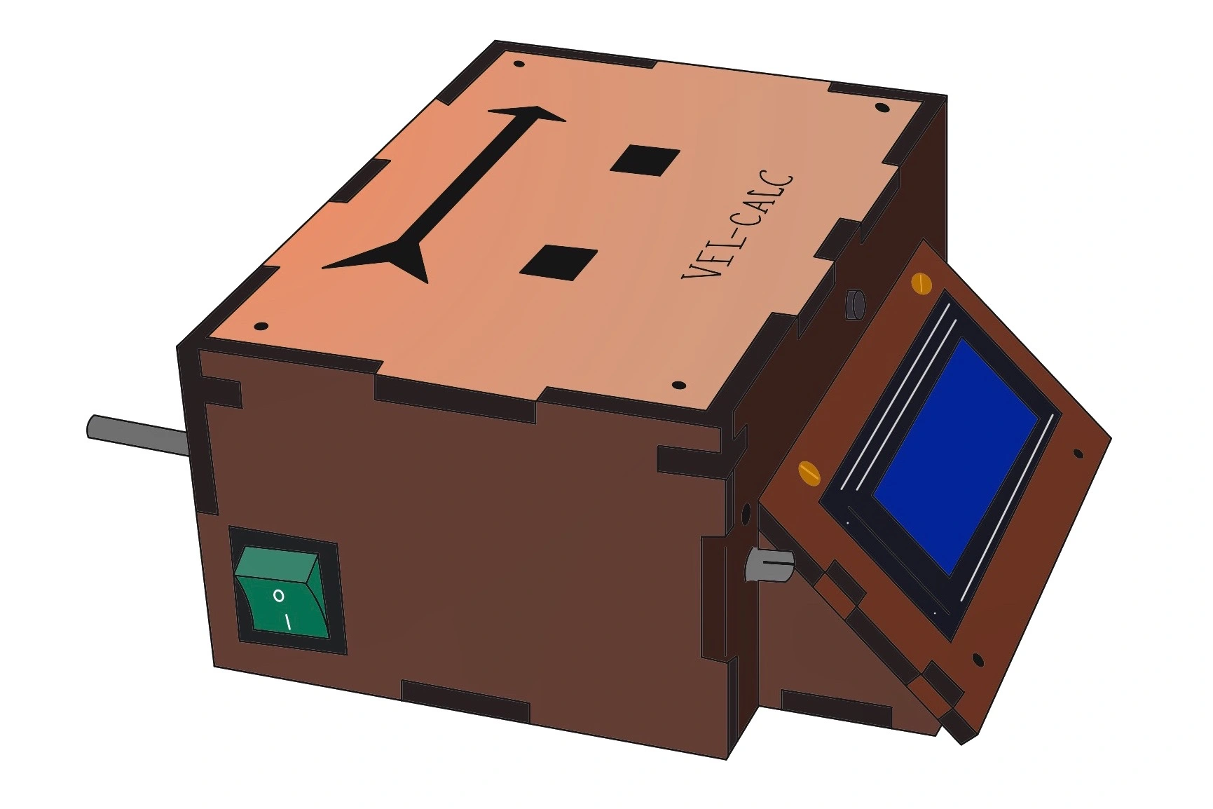
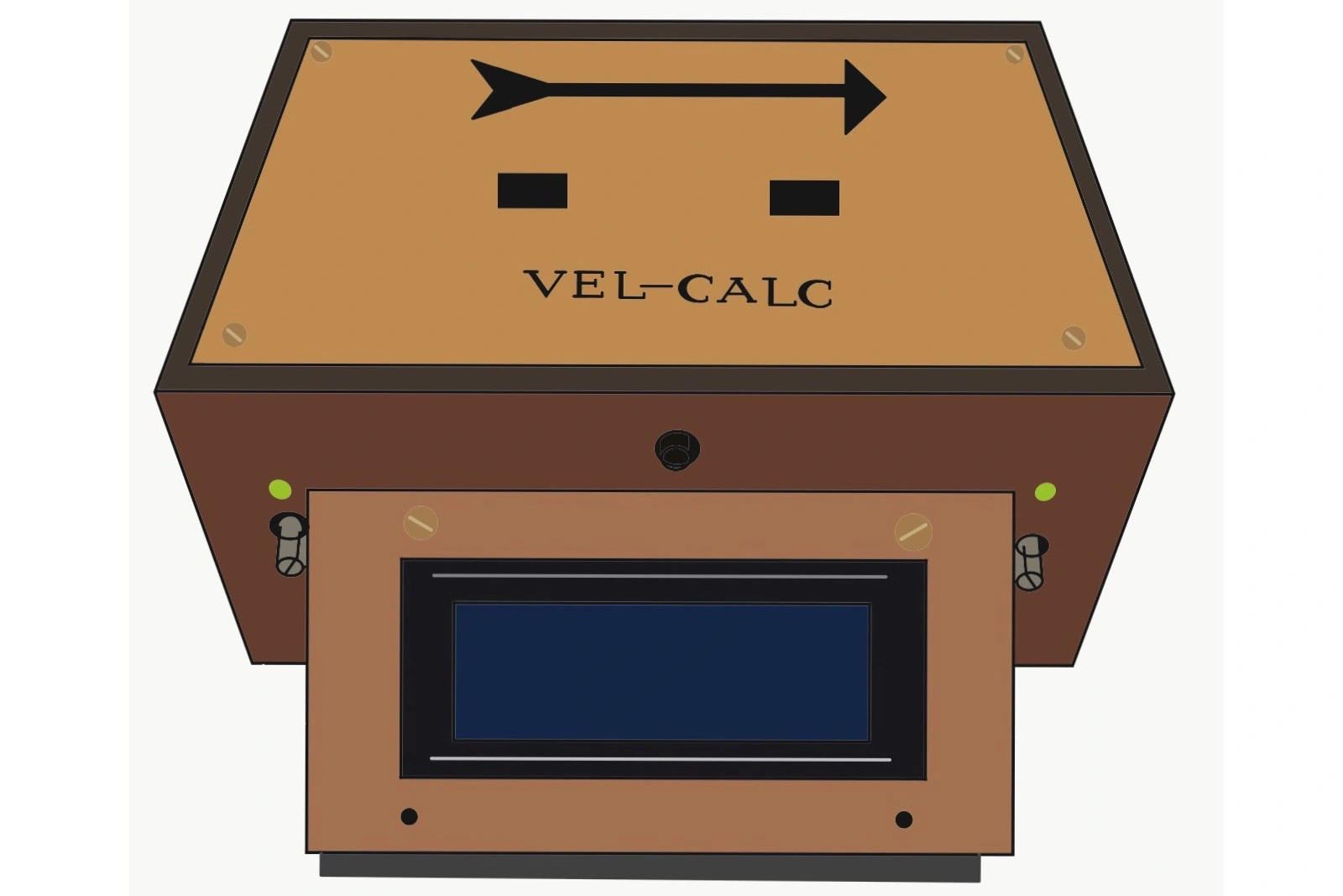
Vel-Calc
Vel-Calc is a device that measures the velocity of any moving objects under the presence of adequate lighting. This project was initially initiated to be used for laboratory purposes where measuring accurate velocities may be a necessity. However, unlike a light-gate, Vel-Calc can even be used to measure the speed of larger bodies such as a person or a car while also being cost efficient. Built and tested in the premises of National Innovation Center - Tribhuvan University, this self-led project took about a month to complete and have its accuracy tested.
Vel-Calc is based on the intensity of light it receives. When an obstruction comes in between the light sources and Vel-Calc light sensors, the electrical signals fluctuate causing the built-in microcontroller to respond accordingly. This way when the shadow of an obstruction hits the first sensor, a timer is activated; when the shadow obstructs the second sensor, the timer stops. Since the distance between two sensors is a known value, the microcontroller calculates and displays the velocity of the object that passed.
Hardware
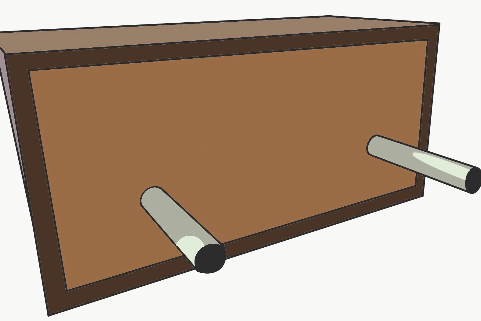
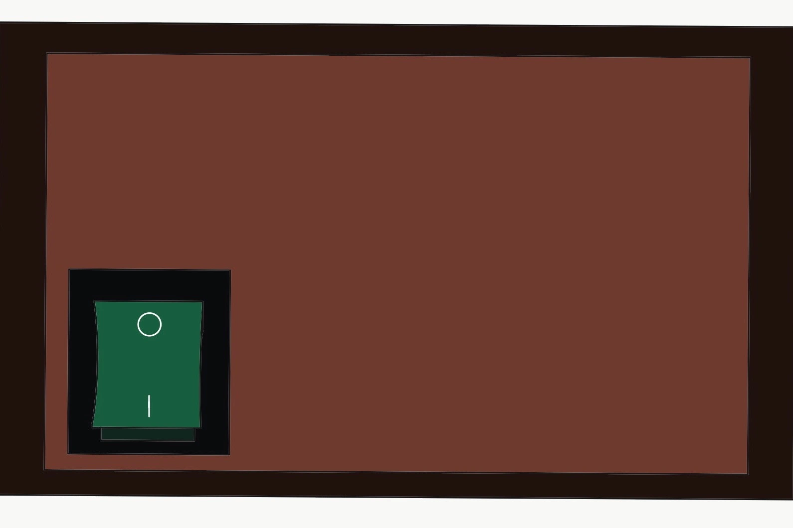
The chassis of the first prototype of the Vel-Calc has a classic wood finish. However, the succeeding models are being built using acrylic for durability. While the circuit functioning is controlled using Arduino Nano, the operation happens due to the vital role played by LM358P. LM358P is a dual operational-amplifier (OP-Amp) integrated circuit which works on the principle of an OP-Amp. The two sensors used are both Light Dependent Resistors. The specific potentiometers for both the sensors are used to control the intensity of light that is received and is indicated using the LEDs present on the either side of the display. All components are soldered into a circuit matrix which is operated using a 9V battery.
Electronics
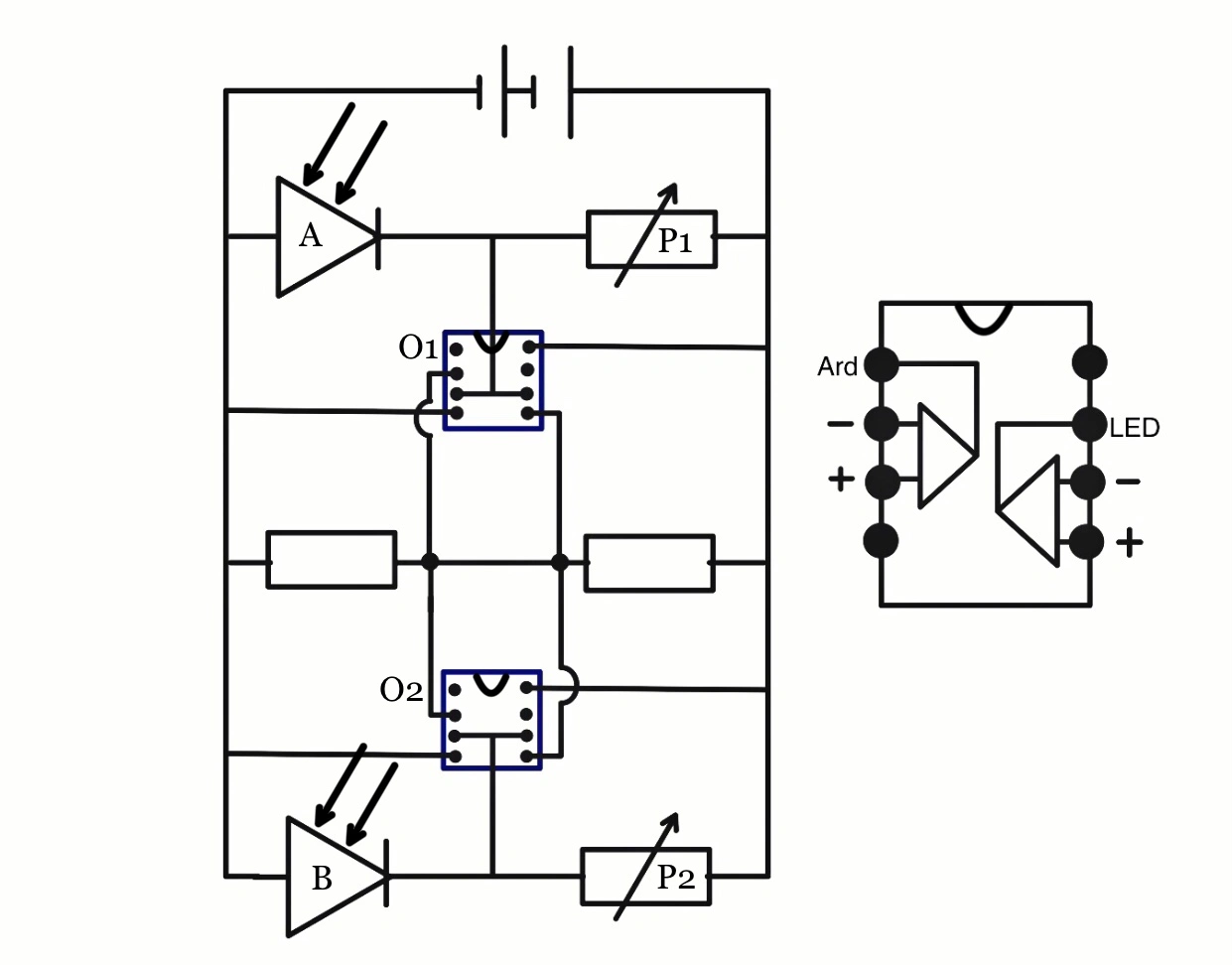
In the given diagram, A & B are Light Dependent Resistors (LDR). If the device calibration is completed, there should be lazer beams striking on both LDRs. This makes the resistance of both LDRs very low : almost equal to 0. This low resistance causes the given comparator circuit to output a continuous electrical signal equivalent to 0 Volts at O1 & O2. This 0V signal becomes the input to Arduino which considers this 0V signal as digital/binary 0. When any object passes through either of the LDRs, it breaks the lazer - photoresistor connection. Thus the resistance at A & B increases and causes the output signal at C and D to be equal to the supplied voltage (here : 9 Volts). This change in voltage causes the digital/binary signal read by Arduino changes from 0 to 1. The time taken between subsequent signal changes causes the Vel-Calc to calculate the required velocity. As soon as Arduino reads the signal at O1/O2 as 1, it records the time(T1) at which the change occured using the built-in quartz crystal oscillator. After the first change in signal at either O1 or O2, it waits for next signal change and as soon as it detects second signal alteration to 1, it records the time(T2) at which the change occured. The difference between two recorded time is given by |T1 - T2|. This result divides the known distance 'x' between two photoresistors and displays the resulting velocity on the LCD screen. The LEDs present in the device help to ensure whether or not the resistance of LDRs are low as expected. Lit up LED indicates that Vel-Calc has a strong laser-sensor connection and is ready for measurements. Potentiometer P1 & P2 can be adjusted as necessary to ensure proper functioning of Vel-Calc in any lighting conditions such as a bright room or a disco with fluctuating lights.
#include <LiquidCrystal_I2C.h>
LiquidCrystal_I2C lcd (0x27, 20, 4);
float T2 = 0;
int GateB = 3;
int ReadyButton = 8;
TABpinMode(GateA, INPUT_PULLUP);
TABpinMode(GateB, INPUT_PULLUP);
TABpinMode(ReadyButton, INPUT_PULLUP);
TABWire.begin();
TABlcd.init();
TABlcd.backlight();
}
TAB.
TAB.
TAB.
}
AState1 = digitalRead(GateA);
BState1 = digitalRead(GateB);
AState1 and BState1 holds the value of initial state of two LDRs. Both are 0 when both LDRs are stroke with lazer beam.
TABT1 = (millis())/(1000.);
TABAState2 = 1;
}
if(BState1 == 1 AND BState2 == 0){
TABT2 = (millis())/(1000.);
TABBState2 = 1;
}
millis() function provides the current value of built-in quartz crystal.
TABfloat Velocity = (Distance)/(T2-T1);
TABX1 = 1;
}
if(BState2 == 1 AND AState2 == 1 AND T2 < T1 AND X2 == 0){
TABfloat Velocity = (Distance)/(T1-T2);
TABX2 = 1;
}
TAB//Initializing all values
}
Programming
Vel-Calc has a microcontroller, Arduino Nano, which has been programmed using Arduino C++ Language. When either of the light sensors (LDRs) detect shadow, the state of the built-in timer is stored - using the Arduino millis() function - giving us the final time value after the subtraction of the two recorded time values. Since the two sensors are placed exactly 10cm apart, the intended velocity is calculated by dividing 0.1m by the obtained time(in seconds). Additionally, “Wire.h” module has also been imported to cooperate with the I2C Module LCD which displays the time and velocity of the object.